- Supported hypervisor versions
- 9800-CL virtual machine requirements
- 9800-CL vCPU allocation
- High Availability
- 9800-CL file format options
- 9800-CL network interface mappings
- Secure Boot
- Design considerations with VMware VM operations
- Using SR-IOV interfaces
- Snapshot
- vMotion
- Using the ESXi embedded web GUI
- Deploying the OVA to ESXi with vCenter Server
- Scale for the virtual 9800-CL on Linux KVM
- Prerequisites before installing KVM
- Required packages for KVM
- KVM networking
- Creating and launching a VM
- Attaching to an existing VM using the CLI
- Attaching to the 9800-CL using the Virtual Machine Manager
- Creating the Catalyst 9800-CL VM using the virt-manager GUI tool
- Scale for the Virtual 9800-CL on Hyper-V
- 9800-CL file format options
- Bring up Hyper-V
- Hyper-V networking
- Creating the Catalyst 9800-CL VM using the Hyper-V Manager GUI tool
- The network adapter needs to be configured as a trunk port (normally for GigabitEthernet2):
- Overview of Cisco NFVIS software
- Scale for the virtual 9800-CL on Cisco ENCS NFVIS
- Installation procedure
- Uploading the image on NFVIS
- Creating a network
- Deploying the 9800-CL virtual controller on NFVIS
- Enable serial console access
- Viewing VM resource allocation
- Viewing VM statistics
- 9800-CL DAY 0 CLI configuration setup wizard
- Configure the basic 9800-CL settings
- 9800-CL DAY 0 WebUI configuration setup wizard
- Configuring the 9800-CL via the CLI: Skipping the DAY 0 guided flow
- Embedded web GUI
- vCenter
- SR-IOV (single-root I/O virtualization) introduction
- Enabling SR-IOV on the C9800-CL on ESXi
- Verified and recommended software versions
- All 9800-CL deployments except those using the OVA file with vCenter
- 9800-CL deployments using the OVA file with vCenter
This document provides installation guidance for the virtual Cisco ® Catalyst ® 9800-CL Wireless Controller for Cloud with VMware ESXi, Linux KVM, Microsoft Hyper-V, and Cisco 5000 Series Enterprise Network Compute System (ENCS) Network Function Virtualization Infrastructure Software (NFVIS). The document:
● Provides an overview of the virtual deployment options
● Provides instructions for configuring and setting up the virtual wireless controller.
Supported hypervisor versions
For the supported hypervisor versions for the 9800-CL private cloud, please see the release notes for the required Cisco IOS ® XE version here: https://www.cisco.com/c/en/us/support/wireless/catalyst-9800-series-wireless-controllers/products-release-notes-list.html
The table below shows an example of the Cisco IOS XE 17.6.x release train.
Table 1. Supported hypervisor versions for the 9800-CL private cloud running 17.6.x.
VMware ESXi
ESXi vSphere: 6.0, 6.7, and 7.0
ESXi vCenter: 6.0, 6.5, 6.7, and 7.0
Red Hat Enterprise Linux: 7.6, 7.8, and 8.2
Ubuntu: 16.04 LTS, 18.04 LTS, 20.04.5 LTS
Microsoft Hyper-V 1
Microsoft Windows Server: 2016 or 2019 (Standard, Enterprise, and Datacenter)
Hyper-V Manager: 10.0.14393
Cisco NFVIS
Release 3.8.1 and 3.9.1
1 Supported only on Cisco IOS XE Amsterdam 17.1.1 or later9800-CL virtual machine requirements
Scale and sizing suggest the minimum virtual resource requirements in the table below.
Table 2. Minimum virtual resource requirements for small, medium, and large configurations
Existing supported templates pre Cisco IOS XE Release 17.3
Templates added as part of Cisco IOS XE Release 17.3
Minimum number of vCPUs 1 (hyperthreading is not supported)
Minimum CPU allocation (MHz)
Minimum memory (GB)
Required storage 2 (GB)
Virtual NICs (vNICs)
( * ) Third NIC is for High Availability
Linux KVM vNIC
Linux bridge (brctl)
Linux bridge (brctl)
Linux bridge (brctl)
Linux bridge (brctl)
Linux bridge (brctl)
Linux bridge (brctl)
KVM NIC virtualization
Hyper-V vNIC
Hyper-V NIC Virtualization
Maximum access points
Maximum clients supported
vMotion, vNIC teaming, Snapshot, DRS 3
VMware tools
Layer 2 link aggregation LAG 4
1 To avoid stability and performance issues, it’s advisable to fully reserve the vCPU resources needed for the 9800-CL and never oversubscribe them. Hyperthreading is not supported and will need to be disabled on the host machine.
2 Starting from Cisco IOS XE Amsterdam 17.3.1, the required storage has increased from 8 GB to 16 GB. If upgrading to Cisco IOS XE Amsterdam 17.3.x from a previous release, the existing storage can be kept at 8 GB. For all new installations, it is required to go to 16 GB.
3 The VM operations are supported with some design considerations. Please see the section Design considerations with VMware VM operations.
4 Support for Layer 2 LAG starts in Cisco IOS XE Bengaluru 17.5.1 and supports deployments with single-root I/O virtualization (SR-IOV).
9800-CL vCPU allocation
The 9800-CL vCPU allocation for control plane and data plane processes is shown in the table below.
Table 3. 9800-CL vCPU allocation for small, medium, and large configurations
OVA template size
Total number of vCPUs
Small
(Low throughput)Small
(High throughput)Medium
(Low throughput)Medium
(High throughput)Large
(Low throughput)Large
(High throughput)High Availability (HA) is supported on the 9800-CL VM hosts using virtual redundant ports, in a stateful switchover (SSO) configuration as well as in an N+1 configuration.
9800-CL file format options
Catalyst 9800-CL deployment OVA template (OVA)
Catalyst 9800-CL deployment image
Catalyst 9800-CL upgrade and patches (bin)
9800-CL network interface mappings
The Catalyst 9800-CL maps the GigabitEthernet network interfaces to the logical vNIC name assigned by the VM. The VM in turn maps the logical vNIC name to a physical MAC address.
When the Catalyst 9800-CL is booted for the first time, the router interfaces are mapped to the logical vNIC interfaces that were added when the VM was created. The figure below shows the relationship between the vNICs and the Catalyst 9800-CL interfaces.
By default, the 9800-CL comes with three network interfaces. Below is an example of interface mapping:
● GigabitEthernet1 > Device management interface: Map it to the out-of-band management network. This is the equivalent of the service port on the physical appliance.
● GigabitEthernet2 > Wireless management interface: Map it to the network to reach APs and services. Usually, this interface is a trunk to carry multiple VLANs.
● GigabitEthernet3 > High Availability interface: Map it to a separate network for peer-to-peer communication for HA SSO. This is the equivalent of the RP port. This port is not needed if HA SSO is not going to be configured.
Note: Do not connect two interfaces to a single network, as that may cause network loops. When a trunk port is used, you must either prune VLANs from vCenter or have the GigabitEthernet interfaces in a different vSwitch.

Mapping the vNICs to the Catalyst 9800-CL interfaces
The figure below shows an example of mapping the hypervisor physical port (vmnic2, connected to a switch trunk) to vSwitch0, as intended for the 9800-CL VM management interface, in ESXi. An optional interface intended for use in the redundant HA configuration (vmnic3) is named RP and mapped to vSwitch3.
Note: When testing two 9800-CL controllers in the same Cisco UCS ® server and using RP ports for HA, it is not necessary to connect the physical RP mapped physical adapters at all. However, if active and standby 9800-CL controllers are on separate hypervisors, the RP mapped physical ports need to be connected to the network and must be Layer 2 adjacent and reachable by each other.

Mapping the hypervisor to the VM management interface in ESXi
By default, a hypervisor vSwitch is configured to reject promiscuous mode. If the 9800-CL is using tagged traffic (for a management VLAN, AP VLAN, etc.) via the management port, promiscuous mode needs to be set to accept in order for the vSwitch to carry tagged traffic.
Starting with Cisco IOS XE 17.6.1, Secure Boot deployments of the 9800-CL VM hosts are supported.
Design considerations with VMware VM operations
When deploying VMware VM operations such as vMotion, DRS, Snapshot and vNIC teaming, there are a few design considerations to take into account.
Using SR-IOV interfaces
If SR-IOV interfaces are deployed with the 9800-CL, none of the VM operations are supported. This is due to how SR-IOV works within ESXi as documented at https://docs.vmware.com/en/VMware-vSphere/7.0/com.vmware.vsphere.networking.doc/GUID-E8E8D7B2-FE67-4B4F-921F-C3D6D7223869.html
When taking a snapshot, there is a chance the controller might crash. To avoid this, we recommend configuring RAID0 on the Cisco UCS for both SSD and HDD.
Note: Cloning from snapshots is not supported.
When deploying vMotion on the 9800-CL in standalone mode, vMotion will work without caveats.
However, when the 9800-CL is deployed in HA SSO, there are a few considerations to take into account.
● Do not run vMotion on both the active and standby VMs at the same time. In the time it takes for the active and standby to move to the new hardware resource, the 9800-CL may be seen as going down.
● When using vMotion with 9800-CL in HA SSO, there will be an extended data outage if no packets originate from WLC. This is due to a limitation in ESXi for Virtual Guest Tagging (VGT mode). As a workaround, a continuous ping will need to be initiated from the 9800-CL to update the MAC address in the right port on the physical switch. For more details, see https://kb.vmware.com/s/article/2113783?lang=en_US.
The provided OVA file package can be used to deploy the Cisco wireless controller to the VM. The OVA package includes an OVF file that contains a default VM configuration based on the Cisco IOS XE release and the supported hypervisor.
The following considerations apply when deploying the OVA package to the VM:
● The single OVA package creates a VM with options for three types of virtual wireless controllers, small, medium, and large. Selecting a profile specifies the required virtual CPU and memory. The hard disk requirement will be the same—16 GB—for any wireless controller type. We do not recommend changing the virtual CPU and memory configuration after deployment.
● When deploying using the OVA template, the VM will bootstrap with three interfaces: one is for out-of-band management, one is for wireless management (usually mapped to a trunk interface on the switch side), and the third is for HA to connect to the SSO peer.
● The installation process can be monitored using the virtual VGA console or the console on the virtual serial port. A virtual serial port is optional and can be added after deploying the OVA. At first customer shipment (FCS) the serial console port is not supported for large-scale deployments. If the serial port is required, please see Appendix B: Adding a virtual serial port in ESXi.
Using the ESXi embedded web GUI
VMware ESXi provides a direct deployment of the virtual Catalyst 9800-CL wireless controller without bootstrap customization (see Deploying the OVA to ESXi with vCenter Server).
Perform the following steps in the VMware GUI.
Step 1. Log in to the VMware embedded GUI at https://ESXi_Host_IP.
Step 2. From the Host page, choose Create/Register VM.

Step 3. In the New virtual machine wizard, select Deploy a virtual machine from an OVF or OVA file. Click Next.

Step 4. Enter a name for the 9800-CL VM and select the OVA file that will be deployed. Click Next.

Step 5. Select the datastore for the VM’s configuration files and virtual disks. Click Next.

Step 6. In the Network mappings section, allocate one port group for each of the required network interfaces.

Note: Please refer to Appendix A: Creating a port group in ESXi for steps to configure the port groups for the VM.
Note: SR-IOV interfaces are high-performance interfaces possible in certain Intel ® NIC cards. Refer to Appendix C: Enabling and using the SR-IOV NIC in ESXi to see how to enable and attach them to the 9800-CL.
Step 7. In the Deployment type section, select the desired hardware configuration (AP and client scale) template from the drop-down menu.
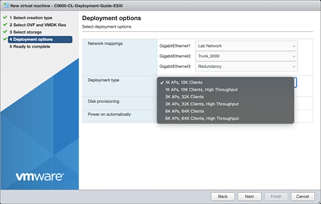
Step 8. The rest of the settings in the Disk provisioning and Power on automatically sections can be left at their defaults. Click Next.

Note: If using the virtual serial port, uncheck the box for Power on automatically, and refer to Appendix B: Adding a virtual serial port in ESXi (optional).
Step 9. Confirm the configured settings. Click Finish to deploy the OVA.


Step 10. Once the VM is finished deploying, select the 9800-CL VM and open the console.

Step 11. Go to the Configuring the 9800-CL section.
Deploying the OVA to ESXi with vCenter Server
VMware vCenter has a flow similar to that of standalone ESXi, except for the ability to customize and bootstrap the virtual wireless controller with login and network information so that the Command-Line Interface (CLI) is not needed at all.
Step 1. Log in to vCenter and choose Launch vSphere Web Client (HTML5).

Step 2. Select Actions à Deploy OVF Template.

Step 3. Enter the URL where the OVA file can be downloaded or select Local file and choose a file. Click Next.

Step 4. Enter a name and select a location for the VM. Click Next.

Step 5. Select which ESXi host to deploy the 9800-CL on. Click Next.

Step 6. Verify the details of the template. Click Next.

Step 7. Select the configuration (AP and client scale) template. Click Next.

Step 8. Select the storage. Click Next.

Step 9. Map the virtual network interface(s) and click Next.

Step 10. As was mentioned earlier, vCenter deployment provides an option to customize or bootstrap the Catalyst 9800-CL wireless controller with a hostname, network configuration, and login. Go through the steps to provide any necessary information using the provided template, and click Next.

Note: When specifying the device management interface, choose the interface mapped to the out-of-band management network. It will be configured as a Layer 3 routed interface with the IP address provided in this step. The network entered in step 2.4 is the remote network from which the 9800-CL will be managed. This will create a static route to that specified network.
Note: When deploying the OVA via vCenter, the configuration bootstrap will always get applied, so “ wr erase ” and “ reload ” will not bring the box to the default configuration. If the deployment does not require bootstrapping or if the 9800-CL needs to be reset to the factory default, please do not power on the 9800-CL after deploying, and refer to the steps in Appendix E: Resetting the 9800-CL to the factory default.
Step 11. Finally, review the configuration data. Click Finish to deploy the 9800-CL in vCenter.

Step 12. Select Power on after deployment.
Note: If you are removing the configuration bootstrap, please do not power on the 9800-CL after deploying and refer to the steps in Appendix E: Resetting the 9800-CL to the factory default.

Step 13. Go to the Configuring the 9800-CL section.
Step 1. Copy the 9800-CL ISO file into the datastore.
Step 2. Create a new virtual machine and choose the OS family/version as suggested below.
● Compatibility: Required ESXi version
● Guest OS family: Other
● Guest OS version: Other (64-bit)

Step 3. Select the datastore for deploying the 9800-CL.

Step 4. Choose the CPU, memory, and hard disk size depending on the deployment requirements. Refer to the virtual machine requirement and scale shown earlier in Table 2.

Step 5. Add the required network adapters and select the port groups needed. Ensure that the network adapter type is VMXNET 3.

Step 6. Ensure that the CD/DVD drive is set to Datastore ISO File and that the Status is checked for Connect at power on. Select the ISO file for the 9800-CL. Click Next.

Step 7. Review the configuration and click Finish. Start the VM.
Step 8. After ISO installation, walk through the initial setup wizard and configure SVIs, wireless interface, trustpoint, etc. (Review the previous sections, as these will be the same.)
Step 9. Go to the Configuring the 9800-CL section.
The virtual Cisco Catalyst 9800-CL Wireless Controller for Cloud can be deployed in Linux KVM using an ISO file (downloaded from the Cisco website), with support for the following distribution:
● Red Hat Enterprise Linux (RHEL) 7.1 or higher
● Ubuntu 16.04 LTS or higher
This guide will not cover every aspect of Linux or KVM components, only the general set of instructions needed to deploy a virtual wireless controller on KVM.
Table 4. Minimum virtual resource requirements for small, medium, and large configurations
Existing supported templates pre Cisco IOS XE Release 17.3
Templates added as part of Cisco IOS XE Release 17.3
